METHODOLOGY part 1
Introduction to the issue of assistive listening technologies, including induction loops
New trends in the use of induction loops to minimize the communication barriers between the hearing impaired and intact society
Methodology for educating professionals and the general public.
Author: collection of authors
This methodology was created as part of the project
“New trends in inclusive education on the use of induction loops (IL) to minimize communication barriers between people with hearing impairment and intact society”
2022-1-CZ 01- KA220 – ADU 000085158
implemented within the ERASMUS+
© Union of the Deaf Brno z.s., 2023
![]()
Part 1
Basic information – general, technical, legislative, implementation, operational.
Who is it for:
For laymen and educated laymen in assistive listening technologies. For those who are interested in this issue either for personal or family reasons, for work reasons or for social and legislative reasons.
Contents of Part 1:
1. General introduction to the issue of assistive listening technologies
1.1 What are assistive listening technologies
1.2 Why, what and whom they are used for
2. How it all began
2.1 A brief look at the history of induction loops
2.2 Some basic theory
2.3 And how it looks in practice
3. Types of inductive listening loops
4. Comparison of IL technology with other assistive sound systems
5. Brief overview of standards and regulations for design, assembly and maintenance of IL
6. Key requirements for auditory induction loop systems
6.1 Increasing the signal-to-noise ratio
6.2 Basic types of transmitting induction loops
6.3 Appropriate IL signal coverage in the given space
6.4 Resiliency to background noise interference
6.5 Generating the correct field strength
6.6 Uniform distribution of field strength
6.7 Flat frequency response
7. Summary of Part 1 of the methodology
Instructional video section – examples of good and bad practice
1. General introduction to the issue of assistive listening technologies
1.1 What are assistive listening technologies
Assistive listening systems are technical devices that help people with hearing impairment to better understand the spoken word, to listen to music, warning signals and other sound information in a better quality. According to the legislation in force in the partner countries of the project and within the EU, persons with hearing impairment, as well as persons with other types of disabilities, have the right:
- to be equal before the law without any discrimination towards members of the intact (able-bodied) society
- to achieve whatever level of education and social status they desire through inclusive education
- to fully participate in social, sports and cultural events and programs
- to have full access to common information through existing technologies and through technologies that will be used in the future, without having to draw attention to their disability in any way.
Assistive (auxiliary) sound technologies are used to fulfill this right.
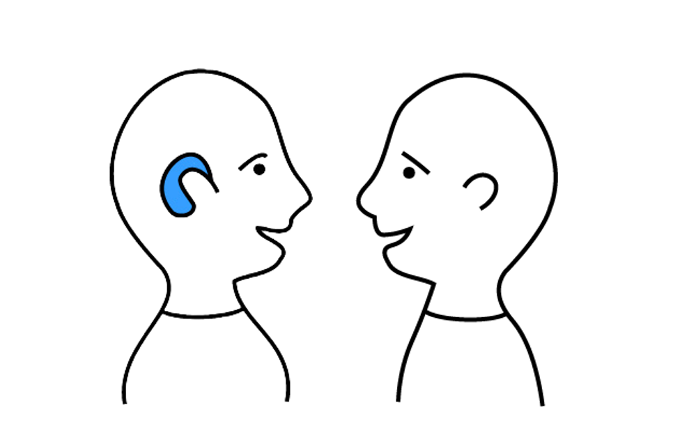
A hearing aid or cochlear implant helps with communication over short distances
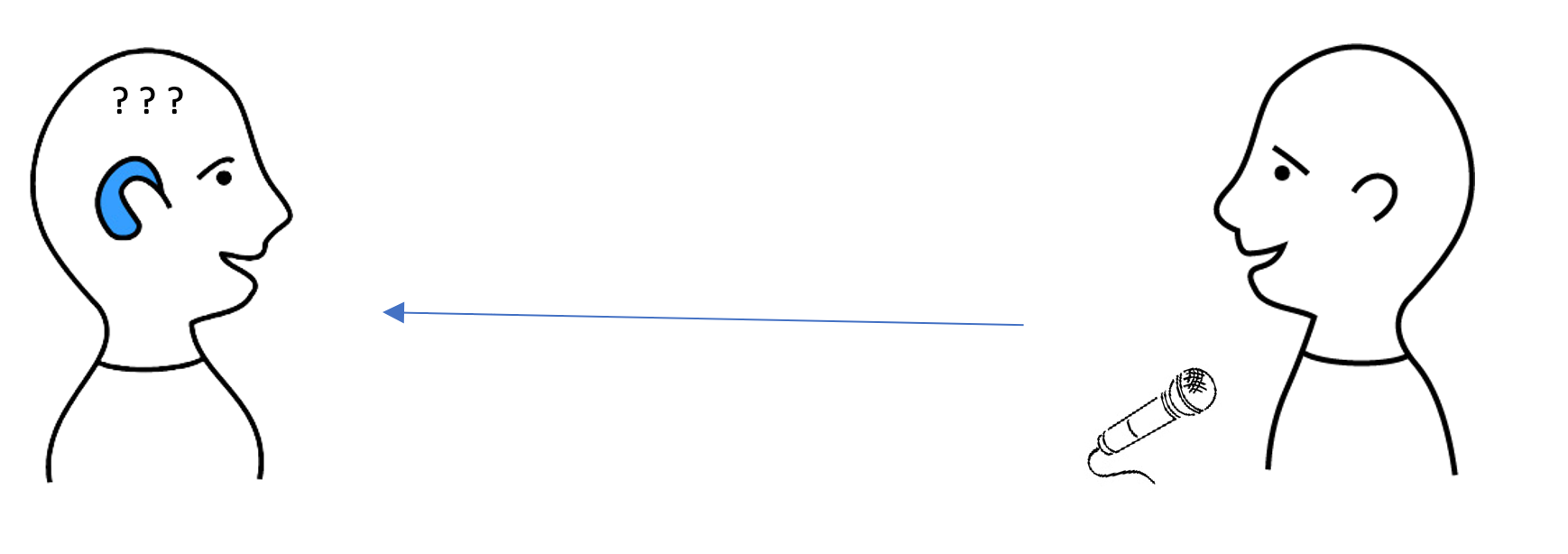
When communicating over longer distances or from speaker systems, a hearing aid is powerless
1.2 Why, what and whom they are used for
Hearing impaired people who use hearing aids or a cochlear implant to communicate with their surroundings often complain that they have difficulty understanding speech in noisy environments or in spaces with long and strong reverberation. Despite digital progress, even modern hearing aids are only designed for 1:1 communication (so-called face-to-face) over short distances. In a noisy environment, it is difficult or impossible to separate the ambient noise from an audio signal without using some of the other supporting assistive technologies (depending on the distance from the sound source, such as a PA speaker). People who are hard of hearing need the sound signal entering their ear to be an amplified by about 15 to 25 dB (dB = decibel) to achieve the same level of understanding as people with unrestricted hearing[1]. Assistive listening systems, which will be the focus of this project, allow a hearing-impaired person using hearing aids or a cochlear implant to achieve this amplification without the need to amplify a conventional PA system or increase the intensity of voice communication to a level too loud for intact people nearby.
There are a variety of assistive listening technologies available these days, and other appealing innovations are likely to appear on the market. Our project is focused on describing the workings of the most currently used technologies that use an induction loop, radio transmission or infrared transmission to propagate the desired audio signal. A separate subsection presents basic information on the use of the Bluetooth or WiFi computer platform to reduce the communication barrier between people with hearing impairment and mainstream society.
There will be a list of user benefits, but also warnings about the shortcomings of the individual mentioned systems.
[1]
Source: “The Benefits of Assistive Listening Systems” by David Baquise, www.nad.org
Source: World Health Organization (https://www.who.int/health-topics/hearing-loss)
![]()
2. How it all began
2.1 A brief look at the history of induction loops
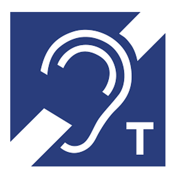
The first magnetic induction loop communication system was invented by Graham Bell. He had a severely deaf wife, and sometimes it is said that his mother was also deaf, and he wanted to help them communicate with their surroundings (the discovery of the induction loop later led to the invention of the telephone). This multi-purpose technology gradually made a significant impact, especially in developing communication aids for people with hearing impairments. Thanks to its efficiency and simplicity, it is currently one of the means of assistance communication most used in the civilized world. The coil in the hearing aid that serves as the induction loop signal receiver is known as a “telecoil” or “T-COIL” because in its early form it processed the magnetic field generated by the speaker in the telephone receiver of a regular telephone. It made it possible to listen to the voice on the phone clearly, unmasked by the surrounding noise. Therefore, the information sign warning that an induction loop is installed at the given location contains the letter “T”. The position of the switch on the hearing aid is also marked, to which the switch must be set when using the induction loop.
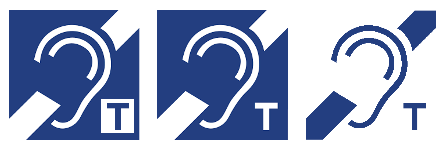
Fig. 1: Information sign – installed IL

Incorrect labeling
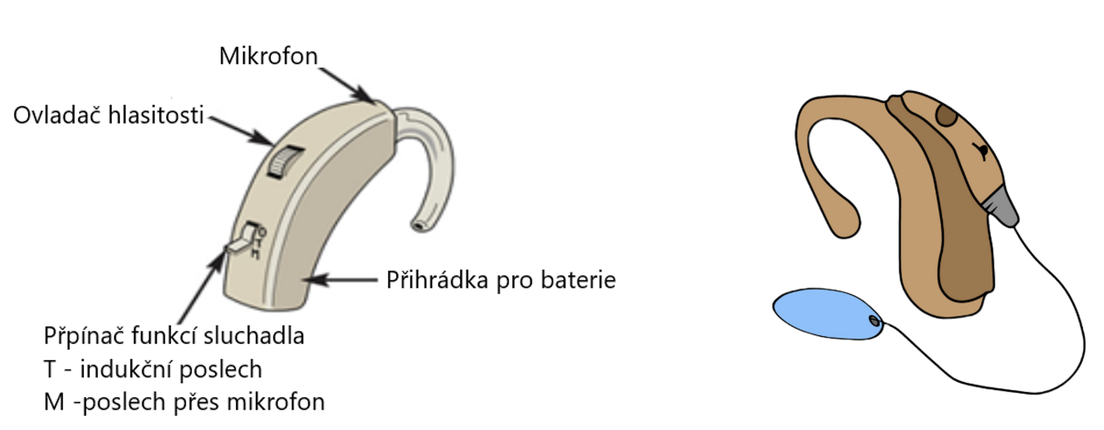
Fig. 2: Hearing aid and cochlear implant with T-switch
The principle of operation of the induction loop (“IL”)

Fig. 3: The coil in the hearing aid records the sound from the magnetic field
2.2 Some basic theory
Induction loop technology is based on the principle of using a variable magnetic field, generated on the transmitting side, to transmit sound information to a receiver. As is commonly known, a conductor/coil through which current flows generates a magnetic field. Its intensity (magnetic induction) depends, in principle, on the size of the current passing through the coil, which induces the field, as well as on the size, shape and design of the coil (if it consists of one turn of the conductor, it is a loop) and on other factors. By modulating these quantities, we can achieve a variable magnetic field in the required space, modulated by the input, in the case of IL, sound signal. On the receiving side, the opposite principle is used. A magnetic field acting on a conductor/coil located in this field causes (induces) an electric current in this coil corresponding mainly, among other factors, to the intensity of the magnetic field in which the coil is placed. If the magnitude of the field changes, the current induced in the receiving coil changes in the same rhythm. This way makes it very easy to transmit various information wirelessly. And so audio information as well.

Fig. 4: Using the induction loop in a lecture room
2.3 And how it looks in practice…
The sound source, e.g., the voice of a speaking person, is transmitted through the microphone to the induction loop amplifier. The same goes for music or other sound from the audio system. An inductive loop amplifier converts the sound source into a variable magnetic field modulated according to the input signal. This magnetic field is propagated by means of a cable sending induction loops to the desired space. There it is wirelessly captured by a T-coil (telecoil) in a hearing aid or cochlear implant. In the hearing aid or cochlear implant, the magnetic field is then converted back into a sound signal.

Fig. 5: Diagram of the induction loop syste
![]()
3. Types of inductive listening loops
Currently, there is a whole range of types of induction loops from personal or simple portable compact devices to advance systems enabling, in accordance with applicable standards (see page 11, chapter 5)) signal coverage of the inductive listening loop of large spaces even in situations where external influences act against the transmission of the magnetic field generated by the loop. In principle, induction loops can be divided according to three criteria:
a) According to the environment in which they work – exterior, hall and counter.
Exterior systems are especially used in sports areas, museums and amusement parks.
Hall systems are mainly used in the following places:
- courtrooms
- lecture halls, classrooms, auditoriums
- conference and meeting rooms
- theaters, cinemas
- religious spaces (churches)
- hotels and hospitality industry
- railway stations and airport terminals
Counter systems:
- contact points, receptions, information stands
- counters in banks, airports, bus and train stations
- hospitals, retirement homes and care services
- retail stores
- TV and home cinema
b) According to the installation method – permanently built-in and portable
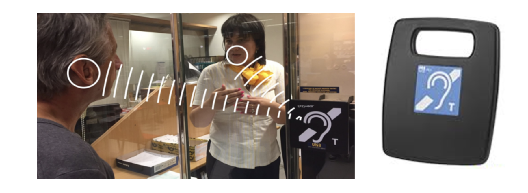
Fig. 6: IL counter at the post office & fig. 7: Portable IL
c) According to the method of use – personal and public/mass use.
Personal IL are used by people with hearing impairments, e.g., at home listening to the television or radio
Public/Bulk IL are installed in places where they are used by several people at the same time (see criterion 1 above)
d) A special group consists of ILs used in transport
These intersect in all the previous categories. For their installation and operation, specific requirements must be met (minimizing signal absorption by metal structures, eliminating very strong fluctuating interference, etc.)
This group includes:
-
- cars Taxi services, buses, trains, trams, trolleybuses
- ticket machines, ATMs, automatic door entry control, elevators and intercom systems
![]()
4. Comparison of IL technology with other assistive sound systems.
This project is primarily focused on the induction loop assistive listening system. However, in order to have a complete and objective view of the world of assistive listening systems, we must also mention other systems that help eliminate the communication barrier between people with hearing impairments and intact society.
These are mainly:
- RF/RADIO TRANSMISSION
- IR/INFRARED TRANSMISSION
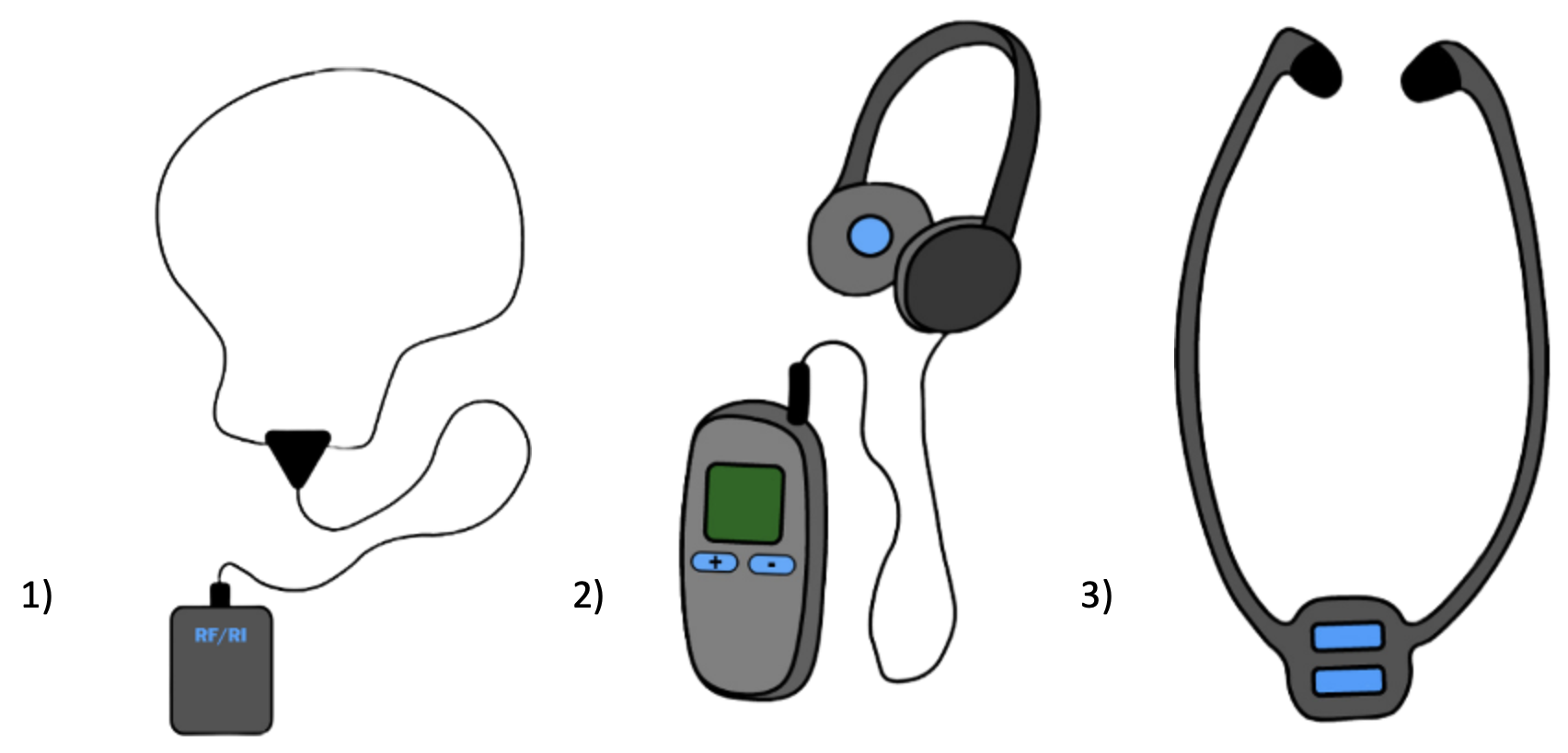
1) RF or RI receiver connected to an induction loop cable around the neck
2) Or with headphones
3) Or stethoscopic RF or RI earphones
- BLUETOOTH (BT)
- WiFi

Fig. 8: Examples of other audio assistive devices
RF/FM TRANSMISSION (RF = radio frequency FM = frequency modulation)
HOW DOES RF/FM TRANSMISSION WORK?
A 2.4 GHz FM radio system transmits the desired audio signal (e.g., a person speaking into a microphone or music from a sound system) via electromagnetic waves. For this, it uses the frequency modulation of the carrier wave at the selected frequency. The receiver is usually a small box with a wire (personal induction loop) around the neck. Through it, the electromagnetic signal received by the receiver is transmitted to the user’s hearing aid or cochlear implant. Using the RF/FM system, the signal can be spread over bigger distances. The disadvantage is that the signal penetrates through the walls and can affect, for example, teaching in an adjacent classroom. It is therefore necessary to tune the system to an unoccupied frequency channel in individual classrooms or other rooms where this transmission is used. Devices of this type make it possible. Another option is to connect a miniature so-called “shoe” to the bottom of the hearing aid. This then transmits the signal to the receiver (T-coil) of the hearing aid or cochlear implant. The RF/FM system can also be used for communication between two people in areas where there is greater disruptive noise.
RF SYSTEM AVAILABILITY
Spaces for which RF/FM equipment is used for assistance sound coverage should be marked with the logo also used to mark induction loops according to the ČSN EN 62489-1 standard.
(More information on this norm is available in the chapter BRIEF OVERVIEW OF STANDARDS AND REGULATIONS FOR IL DESIGN, ASSEMBLY AND MAINTENANCE).
People with hearing impairments must therefore check to see whether the space is marked with the IL logo. In the affirmative case, ask the staff to borrow an FM radio receiver. If the user is using a personal induction loop around the neck, they must make sure to switch the hearing aid or cochlear implant or bone conduction device to “T” or “MT”.
USER EXPERIENCES WITH RF TRANSMISSION
- Hearing aid users must find the device, arrange to rent an FM receiver, and return the receiver with an induction loop around the neck, possibly with a stethoscope or a headset, to the operator after the event. This is often a waste of time for the user
- RF transmission users may end up in areas where the signal is weak, resulting in poorer listening conditions. They may also experience electromagnetic interference
- The RF system is therefore not suitable where it is necessary to walk
- The user of the device is easily identifiable as a person with hearing loss (he has a personal IL around his neck and mostly large unmistakable headphones on his head), which can cause negative reactions from his surroundings
IR/INFRARED TRANSMISSION
HOW DOES IR TRANSMISSION WORK?
An audio signal (e.g., a person speaking into a microphone or music from an audio system) is transmitted to the infrared transmitter. The transmitter converts the sound into the infrared light spectrum and as such transmits it to the desired space. The signal is picked up by a compatible receiver visibly worn by the listener. The receiver decodes the infrared audio signal back to sound, just like the FM system.
The sound from the receiver is transmitted to the hearing aid/cochlear implant via a personal induction loop around the neck (IL).
IR technology requires “line-of-sight” between the transmitter and receiver.
Recently, manufacturers have offered an infrared system capable of spreading the signal to greater distances. For example, in churches, cinemas, etc. Infrared transmission is suitable for both households and institutions. For example, in court, where discreet information is being discussed – the infrared signal does not penetrate walls. On the other hand, it is not suitable in areas where there are many light sources, or outdoors where it can be disturbed by the sun, bright street lights, etc. In the case of IR transmission, multi-channel sound is usually available.
IR SYSTEM AVAILABILITY
Spaces in which IR devices are used for assistive sound coverage should be marked with the logo also used to mark induction loops.
Therefore, keep an eye out for spaces marked IL. Ask the staff on site to borrow a receiver. If you are using a personal induction loop around your neck to connect the IR receiver to your hearing aid, switch your hearing aid or cochlear implant or bone conduction device in the settings to “T” or “MT”.
EXPERIENCES OF IR SYSTEM USERS AND OPERATORS
Since the user generally does not own an IR receiver that would be compatible with the IR system in a given location, he cannot use his own equipment, as is the case with IL, rather he must use equipment borrowed from the IR system operator. It is therefore necessary for users to use the borrowed equipment (receiver, IL around the neck, possibly a stethoscope or headphones) with care.
The user of the device is easily identifiable as a person with hearing loss (he has a personal IL around his neck and mostly large unmistakable headphones on his head), which can cause negative reactions from those around him. The operator must have IL-ready IR receivers and the staff must be trained for these purposes.
WHERE TO USE IR
- Classrooms and courtrooms
- Conference and meeting rooms
- Auditoriums, cinemas and theaters
- Hotels and hospitality industry
- Religious spaces (churches)
- Arenas and indoor stadiums
- Museums
- Retirement homes and care services
- Lounges with TV and home cinema
Manufacturers of assistive listening systems, however, are currently abandoning the production of IR devices.
COMPARISON OF IR AND IL:
Only about 1 in 8 people with hearing loss prefer technology that requires a separate receiver (these are RF and IR technologies).
WARNING:
IHLMA [2] encourages a cautious approach to these technologies for people with pacemakers. Users should maintain a distance of approximately 15 cm between the pacemaker and the induction loop cable around the neck. If in any doubt, consult your doctor.
[2]
IHLMA = International Hearing Induction Loop Manufacturers Association
SOUND TRANSMISSION VIA BLUETOOTH (BT)

HOW DOES AUDIO TRANSMISSION VIA BLUETOOTH WORK?
The primary audio signal, e.g., a person speaking into a microphone or music from the audio system, is transmitted to the audio server, which must be connected to the BT network. This network will provide wireless data transmission of sound signals to the personal devices of users such as tablets and smartphones.
A mobile phone or tablet then uses Bluetooth to transmit sound to a hearing aid / cochlear implant equipped with Bluetooth technology. If Bluetooth technology is not included in the equipment of the hearing aids, then it is possible to use Bluetooth receivers with an induction loop or with a headset.
BLUETOOTH SYSTEM AVAILABILITY
- The event operator must inform visitors in advance to bring their own mobile devices. Tablet or smartphone, or other audio devices communicating with BT
- Provide safe access and instructions to the desired application. Provide alternative receivers for those who do not own a smartphone or tablet
USER EXPERIENCE
- Good for use in sports bars and fitness clubs
- It is not yet widely available as assistive listening
- There can be considerable latency (delay time) between the speaker and the hearing aid
- BT transmission can be used over a distance of tens of meters
USES
- Airports, train stations, bus stations
- Universities and colleges
- Conference halls and meeting rooms
- Auditoriums and theaters
- Religious spaces (churches)
- Arenas and stadiums
- Hotels and hospitality industry
- Hospitals
- Museums
BENEFITS FOR ASSISTANT BT NETWORK OPERATORS
- Smartphones are widely available and widely used by the hearing impaired
- BT provides freedom of movement in a relatively large area (tens of m2) without any fluctuating signal strength
- Multi-channel audio is available
BENEFITS FOR USERS
- BT allows access to different/multiple audio streams
DISADVANTAGES
- It requires a specific application for each network from each hearing aid manufacturer separately
- It is necessary to log in to the BT network with a password – this must be provided by the network operator
- There are no installation standards or sound quality guarantees
- Unless they have their own smartphone or tablet or other Bluetooth-enabled device, users must have Bluetooth-enabled headphones or earphones or an induction loop around their neck to transmit to their hearing aids
- Some hearing aid users do not have the cognitive or physical ability to set up a smartphone or tablet
- There are no peer-reviewed studies available on the benefits of Bluetooth systems for the hearing impaired
Basic slogan:
“Bring your own device” will maintain your privacy and discretion.
NOTE
At the time of working on this project, there has been considerable confusion and ambiguity surrounding Bluetooth technology in the assistive technology world.
Instruction:
Bluetooth Classic is available now and primarily used for personal use, such as pairing hearing aids with mobile phones, TVs and cars.
Currently, hearing aid manufacturers from a number of countries work on largely incompatible platforms. This means, for example, that a personal device for listening to TV via Bluetooth from one manufacturer cannot be used with hearing aids from another manufacturer.
The incompatibility between transmission protocols can cause the signal to drop during transmission, the need to re-establish the connection, or even the complete failure of the audio transmission. A new technology, Bluetooth LE, is being developed to support multi-stream audio for a range of hearing products. For example, in-ear headphones, headsets and over-the-counter hearing aids.
This technology is not yet available, but before that happens, hearing aid manufacturers will need common protocols and standardization across brands.
If common standards and protocols are agreed, then the introduction of this technology will not happen overnight and will have to be developed in stages. The new technology will also need to meet all relevant technical and accessibility standards, including standards for:
- sound quality
- audio latency
- access and availability
- effect on hearing aid function
- access for users without hearing aids
- coverage
- security
- markings and instructions
- monitoring and maintenance
- ompatibility
Like any new technology, Bluetooth LE or its equivalent will need to prove that it is fit for purpose and can benefit the hearing impaired.
Even if Bluetooth LE successfully fulfills the requirements for a fully functional assistive listening solution, the mass transition to such new assistive technology will still take a long time.
SOUND TRANSMISSION VIA WiFi
HOW DOES AUDIO TRANSMISSION VIA WiFi WORK?
WiFi is a system that wirelessly transmits data information between the device of the user of the given network and the Internet. The WIFI standard is used worldwide in home and office networks to connect desktop and laptop computers, tablets, smartphones, televisions, speakers, printers and connect them to the Internet using a wireless router. WiFi is also found in wireless access points in public places such as coffee shops, hotels, libraries and airports that provide visitors with Internet access for their mobile devices. Since WiFi works with data in digital form, digitized audio can also be transmitted using this system. Thanks to the fact that the carrier medium is the worldwide Internet, it is possible to transmit sound over an arbitrarily large distance using WiFi. However, its use as assistive listening for the deaf has many disadvantages, similar to Bluetooth (see the previous chapter). The main problem is that this is a system that was not created for this purpose, and therefore it does not respect the usual need of the deaf user for an assistive device to have simple, intuitive controls. Another problem is the incompatibility between the transmission protocols of different manufacturers, which can cause the signal to drop off during the transmission, the need to repeatedly establish the connection, or even the complete failure of the audio transmission.
However, it can be assumed that in the near future new applications will be created that also address the needs of hearing-impaired people who use hearing aids or a cochlear implant. As is already the case for deaf people who use sign language or the translation of the spoken word into written form to communicate with their surroundings.
![]()
5. Brief overview of standards and regulations for design, assembly and maintenance of IL
a) European standards
Prepared and published by the International Electrotechnical Commission (IEC)

IEC60118-4: Electroacoustics – Hearing aids – Induction loop – hearing aid systems – purposes – system performance.
IEC 60118-0: Electroacoustics – Hearing aids: Measurement of the performance characteristics of hearing aids.
IEC 62489-1: Electroacoustics – Audio-frequency induction loop – Systems for assisted hearing: Methods of measuring and specifying the performance of system components.
IEC 62489-2: Electroacoustics – Audio-frequency systems – Induction loops for assisted hearing: Methods of calculation and measurement of low frequency magnetic field emissions from the loop for assessing compliance with human exposure limit guidelines.
IEC TR 63079: Rules of practice for inductive hearing loop systems (HLS). Wireless microphones; PMSE audio up to 3 GHz; Part 4: Assistive listening devices including personal sound amplifier and induction systems up to 3 GHz.
Note:
The key standard is IEC 60118-4 = International standard IEC 60118-4 is applicable to audio-frequency induction-loop systems producing an alternating magnetic field at audio frequencies and intended to provide an input signal for hearing aids operating with an induction pick-up coil. Throughout this standard, it is assumed that the hearing aids used with it conform to all relevant parts of IEC 60118.
This standard specifies requirements for the field strength in audio-frequency induction loops for hearing aid purposes, which will give adequate signal-to-noise ratio without overloading the hearing aid. The standard also specifies the minimum frequency response requirements for acceptable intelligibility. It specifies the methods for measuring magnetic field strength and the appropriate measuring equipment. Information that should be provided to operators and users of the system and other important information. For example, it specifies the use of the ear logo with the letter – T.
This standard does not specify requirements for loop driver amplifiers or associated microphone or audio signal sources, which are dealt with in IEC 62489-1, or for the field strength produced by equipment, such as telephone handsets, within the scope of ITU-T P.370.
Fundamental rule: If the IL does not work according to the requirements of IEC 60118-4, then it will not work correctly!
b) Standards valid in the Czech Republic:
ČSN EN 62489-1: The standard establishing the method of measuring the electromagnetic signal in a space.
Measurement of input sound value – signal coverage of a space – clear marking of a space covered by IL or other type of assistive listening technology – operator training – equipment monitoring and maintenance
Decree of the Ministry for Regional Development of the Czech Republic No. 398/2009 Coll., on general technical requirements for the barrier-free use of buildings
List of ČSN to Decree No. 398/2009 Coll. – To facilitate actual application, the Department of Building Regulations of the MMR of the Czech Republic keeps a list of Czech technical standards, which is organized according to the individual provisions of the decree containing references to standard values. The file is in the section Ministry – Construction law – Law and legislation – ČSN standards and related information.
http://www.mmr.cz/getmedia/e0adb6e7-1813-4a62-b263-a7c9975e8b93/398-2009_CSN_k2018_05.doc
c) Standards valid in the Slovak Republic:
“Decree of the Ministry of the Environment of the Slovak Republic No. 532/2002, dated July 8, 2002”, which establishes the details of general technical requirements for construction and general technical requirements for buildings used by persons with limited mobility and orientation.
The placement of induction loops is regulated specifically in the annex to the decree: “General technical requirements ensuring the use of buildings by persons with limited mobility and orientation”. The annex mentioned in section 2.4.3. states: “In a designated place of a non-residential building in a part designated for use by the public, the designated place must be equipped with an induction loop for a hearing-impaired person. The place must be marked with the international symbol of deafness.
Decree No. 532/2002 is effective until March 31, 2024. It will then be replaced by Act No. 200/2022 Coll., “on zoning” effective on April 1, 2024.
d) Standards valid in the Republic of Slovenia:
“Zakon o izenačevanju možnosti invalidov” = Act on the equalization of opportunities for persons with disabilities. It proposes that every public institution be barrier-free accessible for various disabilities, including persons with hearing impairment.
“Rules for the universal construction and use of building works.” These rules oblige investors to install IL in every new public building. In older public buildings, IL must be installed during building renovation.
6. Key requirements for auditory induction loop systems
6.1 Increasing the signal-to-noise ratio
The system must significantly improve the signal-to-noise ratio and other distracting audio stimuli. This can be achieved with a regular hearing aid or cochlear implant that is wirelessly connected to the induction loop. If this condition is not met, check the audio input source and select the amplifier and adapters for the appropriate installation. If you are using a microphone as a sound source – then the type and placement of the microphone is crucial.
For area coverage, do not use omnidirectional microphones (especially not in ceiling panels), as they generally achieve a worse separation of signals from distracting sounds and noise than directional microphones. Choose a directional microphone with a cardioid pattern (sometimes the term kidney pattern is also used) or a highly directional hypercardioid (super kidney pattern) microphone with a very narrow catchment field.
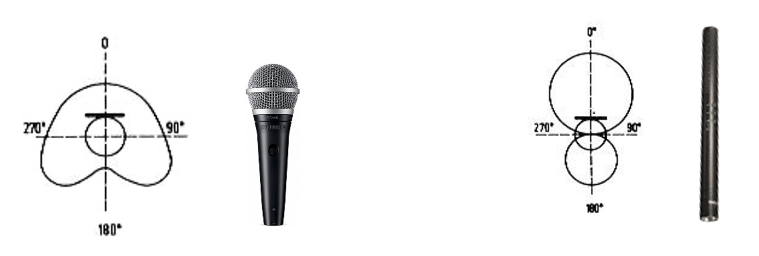
Fig. 9: Cardioid microphone and fig. 10: Hypercardioid microphone
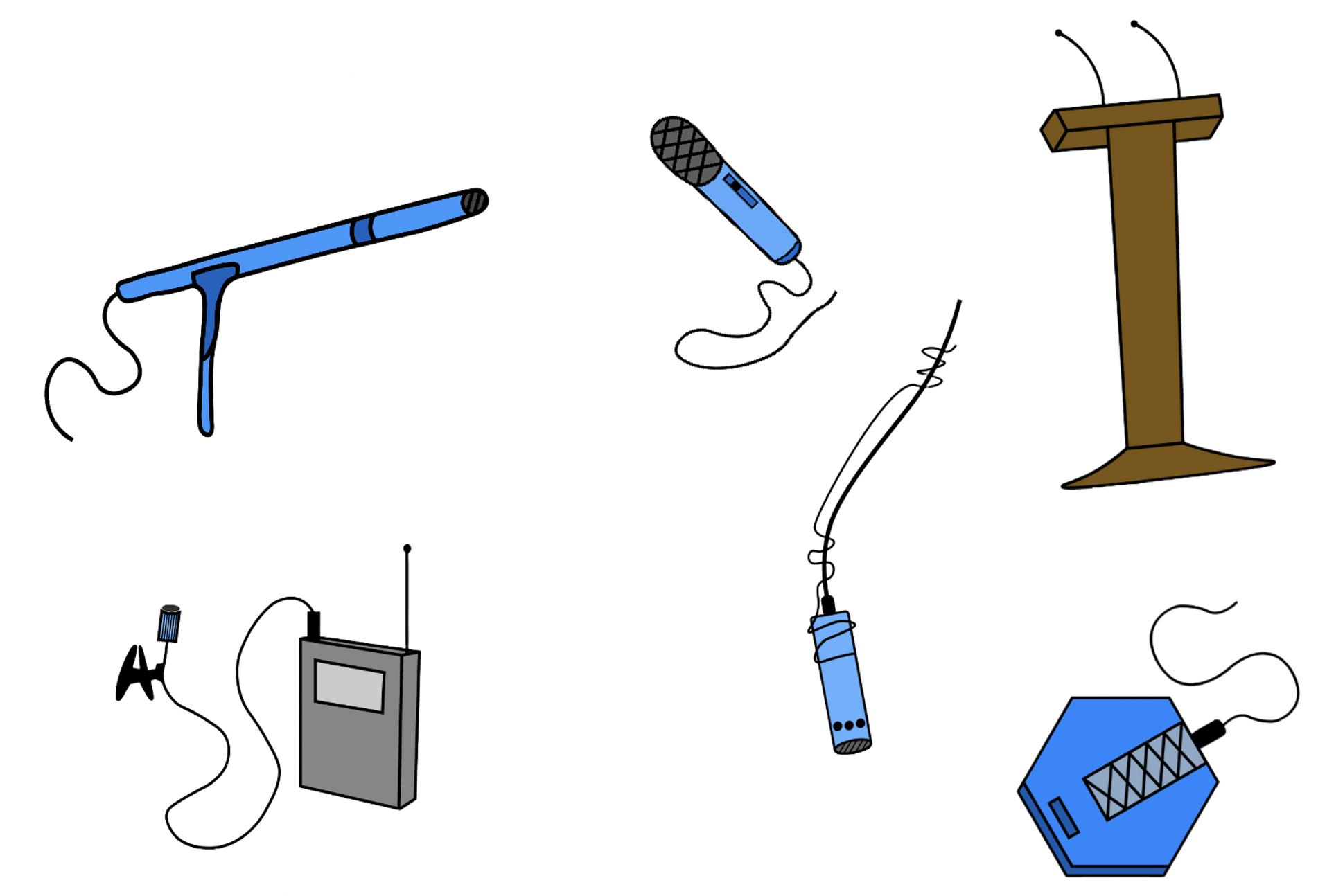
Fig. 11: Other possible uses of microphones
6.2 Basic types of transmitting induction loops
The optimum coverage of the required space with the IL signal is achieved not only by the selection of suitable components, but also by the shape and design of the transmission loop.
Perimeter Loop

Fig. 12: Perimeter loop – small space and fig.13: Perimeter loop – large space
Description:
The simplest IL solution: One loop of a cable or copper tape installed around the perimeter of the area/room to be covered by the IL signal, fed by one loop transmitter.
Application:
Rooms without metal structures with a width of up to 25 m. If there are metal structures in the room or another sound-proofed space, the maximum width decreases to 4 m. If there are large losses in metal structures (for example, a reinforced concrete structure with iron curry nets in the walls), the width drops to 2 m. The system is only useful where signal overspill (i.e., the magnetic field generated by the induction loop can be picked up even outside the desired sounding area) is not a problem, where there are no nearby or adjacent induction loop systems and where confidentiality is not important.
Additional comments:
Large loops cause variations in the signal intensity and thus the listening quality in the area they cover. Very large rooms (width >25 m without metal in the walls, etc.) will have a much lower signal in the center of the covered area than at the outer edge (see Fig: 9). Where metallic structures are present, metal losses will dramatically reduce the field strength towards the center of the loop. With the presence of metal, perimeter loops are usable only in small rooms.
Cancellation Loop

Fig. 14: Cancellation Loop – magnetic field and fig. 15: Cancellation Loop – wire
Top view
Description:
A carefully designed and properly wired segment of the small side loop will eliminate signal leakage from the system in one direction. The small loop is fed from the same amplifier as the main loop. To absorb the signal spillover, this small loop has to work with phase shift, magnitude and variable intensity.
Application:
Rooms suitable for a perimeter loop, but there is a requirement to limit signal leakage (so-called overspill) in one direction (e.g., lecture halls “back-to-back”).
Additional comments::
In fact, canceling an “overspilling” signal outside the desired space usually requires a number of attempts before finding the optimal configuration of the “cancellation” loop. A cancellation loop requires a higher voltage potential in the amplifier than a perimeter loop. There will be a null signal line between the cancellation loop and the main loop – it is important to ensure that there are no users near this null line.
Overspill loop
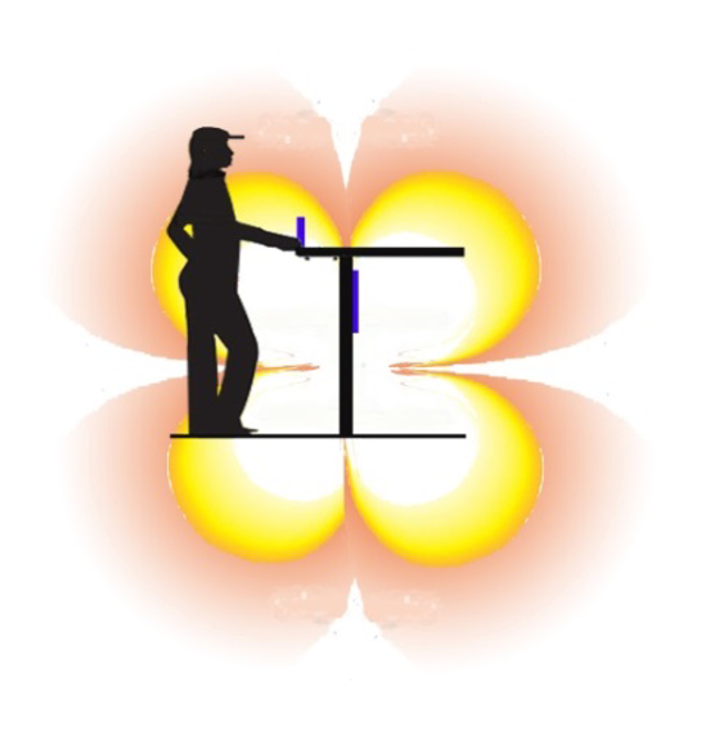
Fig.16: Overspill loop – magnetic field
Description:
A small rectangular loop typically mounted vertically on a panel or wall well above or below head clearance, e.g., under a front panel counter, so that the IL signal is audible at 130-170 cm. It usually contains multiple turns to achieve high field intensity (one turn is possible with specially modified amplifiers).
Application:
Check-in counters, information services, receptions, cash registers and other individual applications.
Additional comments:
Standard preformed multi-turn loop.
It creates a spatially very small magnetic field. It meets the standards specified by the relevant standards (IEC60118-4 and others) up to a space size of approximately 200 x 400 x 400 mm (the covered area is different for different systems from different manufacturers). Only suitable where the user is in a well-defined position relative to the loop. Metal structures or panels can significantly reduce the field strength generated by IL. This problem can be minimized by mounting it so that the upper edge of the loop protrudes beyond the metal panel.
Single Array

Fig. 18: Overlapping loop creating a uniform signal field
Magnetic field – top view
Description + application:
The loop divides the area into smaller rectangles, providing a much more uniform field strength throughout its range. This is especially advantageous for loops that cover large spaces or areas with a signal or where signal losses occur in metal structures. The room must have fixed seating or well-defined areas for users to move around in.
Additional comments:
There will always be a so-called dead line with a zero signal between the loop sections. It is necessary to ensure that users of the loop do not get into it, because then their listening would not be of high quality, or could be zero. This condition can be easily fulfilled by the above-mentioned firm fixation of the chairs, or benches, with the fact that neither chairs nor benches are installed in the areas of dead lines. However, not every space can be fitted with fixed seating. Then there is the problem of marking the “dead spots” and ensuring that no one with hearing aids or cochlear implants stays in them for a long time. Therefore, dividing the space into individual fields is only useful under very specific circumstances. More rectangles mean more cable length, which requires more amplifier power. This needs to be carefully checked already in the project preparation phase.
Low Spill MultiLoop = Loop with very little overspill of the magnetic field

Fig. 19: Distribution of the magnetic field – top view
Description:
A loop with very low information leakage outside the desired area and with uniform coverage of a large area. This effect is achieved in a way similar to the “cancellation loop”. This involves the use of small cancellation loops located on all four sides of the loop array. This is a case of working mainly with phase relationships between individual elements. Uniform coverage is achieved by two overlapping and crossing loops with a basic phase shift of 90°.
Application:
Adjacent classrooms – each with its own IL. Without the use of this system, the signals from both classrooms would cancel or interfere with each other.
Places for confidential meetings (e.g., courtrooms).
Large areas with loss in metal structures / greater than 25 m in width.
Low Loss MultiLoop = Loop with low losses

Fig. 20: Low loss loop – Top view
Description:
This overlapping loop works on a principle similar to the Single Array loop. It divides the coverage area into smaller segments. They are mostly rectangles, the longer side of which is equal to the width of the room or other space covered by the signal. This achieves uniform coverage of the entire space with minimal losses, whether due to metal structures or interference from other electromagnetic affects.
Application:
In spaces where, due to large losses and uneven coverage of the sound space, it is not possible to use the Perimeter Loop. It is used in large spaces, in places where signal overflow (overspill) outside the sound zone is not a problem.
Comments:
To install this loop, two intersecting interleaved loops with a phase shift of 90° are used. For this reason, a double loop amplifier must be used.
6.3 Appropriate IL signal coverage in the given space
Determine what use the proposed IL installation will serve:
- If the proposed space includes fixed seating, the listening height will be approximately 1.2 meters from the ground. This must be accommodated by the system loop design and amplifier power requirements.
- If people use the induction loop system in a standing position, or if people will move freely about in the space, then the listening height will be about 1.6 meters from the ground.
- If the area to be covered by the IL signal contains a stage entertainment area where microphones and electric instruments will be used, then a “Cancellation Loop” or “Low Spill” type loop will be installed with little signal overhang into the space. The installation of an overlapping inductive loop with multiple “Phased Array” (phase shifted) loops is required to prevent signal interaction with electroacoustic equipment on stage.
- The loop should always cover as much available space as possible. Providing a small loop area for hearing aid users (e.g. in the first 5 rows of a theatre) is not an appropriate solution as this often separates the user from their friends and family, which is discriminatory.

Fig. 21: Example of interleaved IL for large spaces with high interference
6.4 Resiliency to background noise interference
Electromagnetic noise can be caused by faulty wiring of either the IL system itself or some electrical appliance on the premises where the IL is installed. Local substations can also contribute to an increased noise level. Noise can affect intelligibility and can also have an uncomfortable effect on listeners.
The actual state of the situation, which allows us to suppress the increased electromagnetic noise, can be determined by the following procedure:
Use a meter to determine how much electromagnetic noise is present in the loop area. It must be less than or equal to -32dB (A-weighted). If the noise level is higher, it is necessary to make the correct setting or repair.
If possible, the noise problem should be addressed at the source. If afterwards the result is not adequate, it is necessary to diagnose and repair faulty cabling or the IL wiring itself.
6.5 Generating the correct field strength
The intensity of the magnetic field transmitting the original sound information must be set to an optimal value. If the field strength is too low, intelligibility and the signal-to-noise ratio will be disrupted. If the field strength is too high, the hearing aid may be overloaded, which will manifest itself in distortion, acoustic feedback (whistling), etc.
The magnetic field strength at the listening plane (ear height) should be 400 mA/m sine @ 1 kHz.
6.6 Uniform distribution of field strength
A loop listening system should provide a constant field strength throughout the space, so that the signal does not vary too much when the users of the system move about. The field strength must remain within a tolerance of ± 3 dB throughout the listening area.
6.7 Flat frequency response
IL induction loop systems can be used to transmit music, human voices, or other sound signals. Human speech produces specific frequencies for forming words. It is necessary for the system to be able to replicate these frequencies in order to maintain the intelligibility of the audio broadcast to the users of the system.
Frequency response 100Hz – 5kHz ± 3dB (a reference level @ 1kHz must be maintained throughout coverage area).
Make sure that the specified amplifier is capable of generating sufficient power and voltage reserve.
Maintain proper field strength.
![]()
7. Summary of Part 1 of the methodology:
- For years inductive hearing loops have proven their use in helping people with hearing impairment overcome the information barrier between them and mainstream intact society.
- Inductive hearing loops offer a technically simple, reliable, efficient and user-friendly system which, without complex technical components or settings, provides the transmission of a useful sound signal from the source directly to the user’s hearing aid or cochlear implant. A hearing aid or cochlear implant serves as a receiver of a variable magnetic field modulated by a transmitted sound signal.
- The only action the user of the hearing aid or cochlear implant needs to take is to flip the switch on the hearing aid to the “T” position.
- Even though the inductive listening loop is in principle a simple device, its design, assembly and adjustment must be entrusted to a specialist company. Induction loop technologies are still undergoing development to provide users with better and better listening, which can correct losses in signal transmission in metal structures, suppress “signal overflow” outside the required spaces, etc. Only a specialist company with experience in the field is able to put these trends into practice.
- The way the loop is made, the power of the loop amplifier, the height of the loop location, etc., these are matters that must be solved directly at a specific location based on the results of primary measurement and testing (see Methodology Part 2, chapter 6). Even this pre-project preparation should be entrusted to experts. Never allow a designer to design an induction loop based only on catalog parameters without thorough on-site preparation.
- List of consulting firms and institutions in the Czech Republic:
UNION OF THE DEAF BRNO s.r.o. – social enterprise, Czech republic
Palackého třída 19/114 – entrance from Kollárova Street (Café u Žambocha), Brno- Královo Pole
Phone: +420 725 605 216 (SMS, Mobil, WhatsUpp), e-mail: info@unb.cz
Eebsite: www.unb.cz
(also operating in Slovakia and Slovenia)
WIDEX LINE spol. s r.o
Bohušovická Street 230/12, 190 00 Prague 9, Czech republic
Phone: +420 286 580 396,+420 605 947 864, e-mail: servis.cz@widexsound.com
Client Center Brno, Hlinky 995/70, 603 00 Brno
Phone: +420 543 331 630, +420 734 738 964, e-mail: brno.cz@widexsound.com
Client Center Ostrava, Biskupská 3330/8, 702 00 Ostrava
Phone: +420 597 317 597, +420 602 167 278, e-mail: ostrava.cz@widexsound.com
- List of consulting companies and institutions in Slovakia:
WIDEX – SLOVTON Slovakia s.r.o.
Client Center Bratislava, Račianska 77 / B Street, 831 02 Bratislava, Slovakia
E-mail: info.ba@widexsound.com
Website: www.widex.com/sk-sk
Phone: 02/ 4488 1203, +421 902 604 047
Client Center Košice, Južná trieda 8 Street, 040 01 Košice, Slovakia
E-mail: info.ke@widexsound.com
Website: www.widex.com/sk-sk
Phone: 055/ 625 3352,+421 917 895 062
AUDIOCARE, Irkutská 8 Street, 040 12 Košice, Slovakia
E-mail: info@audiocare.sk
Phone: +421 950 206 745
- List of consulting firms and institutions in Slovenia:
ELEKTROTEHNIKA ZUPANC, Šlandrov trg 20 Street, 3310 Žalec, Slovenia
Website: elektronika-zupanc.si, e-mail: zupanc18@siol.net
Phone: +386 (3) 5717 484
![]()
END OF PART 1
PART 2 FOLLOWS (see main MENU)