METHODOLOGY part 2
Introduction to the issue of assistive listening technologies, including induction loops
New trends in the use of induction loops to minimize the communication barriers between the hearing impaired and intact society
Methodology for educating professionals and the general public.
Author: collection of authors
This methodology was created as part of the project
„New trends in inclusive education on the use of induction loops (IL) to minimize communication barriers between people with hearing impairment and intact society“
2022-1-CZ 01- KA220 – ADU 000085158
implemented within the ERASMUS+ program
© Union of the Deaf Brno z.s., 2023
Part 2
Project preparation, material security, assembly and setup
of newly realized listening induction loop systems.
Maintenance, measurement, setup and testing of ILs that are already in operation.
Who is it for:
For architects, designers of building equipment, companies installing IL, suppliers of components for their installation, investors in public spaces for the gathering of large numbers of people, maintenance workers for existing IL, and for those who are involved in the testing and settings of IL systems.
Contents of part 2:
1. Guide to the il system according to the type of spaces to be sounded
2. The most common means of making an induction loop + material for induction loops
4. Situations in which mistakes are often made and suggestions on how to avoid them
5. Practical recommendations for selecting and setting up portable induction loops
6. Procedures for evaluating and testing the site where il is installed or where it should be installed
7. Putting the induction loop into operation
Annex to Part 2 of the methodology:
Sound information in transportation (train, tram, metro…)
Current status of the use of il in transport in the partner countries of the project
Other examples of using induction loops outside the area of transport
![]()
1. Guide to the IL system according to the type of spaces to be sounded
Table 1, which is below, gives you typical examples of using the individual types of IL and their components. However, it should be noted at the outset that the listed uses of ILs are indicative only. Each IL installation is an original. This originality is derived from whatever disturbing influences there are on the operation of the IL, how strong they are, and how the IL designer intends to deal with them. For example, listening loops installed in a room with a raised steel floor may require an amplifier up to four times more powerful than a system installed in a church on a stone floor. Therefore, we always recommend contacting the manufacturer to ensure that the individual components of the induction loop are selected correctly. Selecting the amplifier should always be based on the type of loop and its power requirements. This can be calculated from the volume of the space to be sounded (length, width and clearance), the length and type of loop, the length and type of power cable and the expected loss factor due to steelwork. Unfortunately, there is no uniform algorithm applicable to components from different manufacturers, nor is compatibility ensured between components from different manufacturers. We strongly recommend that you select components from one manufacturer for each individual IL application and only specify and combine them. Most of the world’s IL manufacturers offer significant support to their customers in all tasks accompanying the installation of IL. So do not hesitate to consult the manufacturer that you choose to cooperate with on both design issues and the details of the specific solution.
Table 1: Typical uses of individual types of IL and their components
| Specification of the space to be sounded with IL | Recommended type of IL loop amplifier | Recommended type of IL connection |
| Face-to-face communication in a noisy environment, e.g., in meeting rooms, when the place where participants should be is not precisely specified | Portable system table induction loop | Portable compact tool |
| Store with over-the-counter sales | Fixed counter amplifier | IL coil prepared by the manufacturer, or more coils that are part of the delivery – system with signal overlap |
| Reception desk, information service | Fixed counter amplifier | IL coil prepared by the manufacturer, or more coils that are part of the delivery – system with signal overlap |
| Teller in a bank, security window | Fixed non-portable amplifier developed specifically for cash registers and in-line duplex intercom systems | IL coil prepared by the manufacturer, or more coils that are part of the delivery – system with signal overlap |
| A room with a rectangular floor plan with the shortest side less than 4 meters | Single-line connection to the amplifier | Perimetric connection of IL – around the perimeter |
| A room with a rectangular floor plan with the shortest side less than 15 meters, in a building without a metal structure | Single-line connection to the amplifier | Perimetrické zapojení IL – po obvodu |
| A room with a rectangular floor plan with the shortest side less than 15 meters, with a stage for electrical instruments, in a building without a metal structure | Single-line connection to the amplifier | Connecting Cancellation IL – this type of IL cancels the overspill of the signal into adjacent spaces |
| Area with a rectangular floor plan with fixed seating and the shortest side less than 15 meters, in a building with a modern metal structure | Single-line connection to the amplifier | Connecting Phase Array IL |
| Area with a rectangular floor plan with the shortest side longer than 4 meters in a building with a modern metal structure | Dual phase amplifier or 2 amplifiers with master/slave configuration and 90° phase shift | Low Loss MultiLoop connection
See Methodology Part 1, Fig. 15 Multi Loop Phased Array |
| A meeting room with a rectangular floor plan with the shortest side longer than 4 meters, in a building with a modern metal structure | Two-line IL amplifier or 2 amplifiers with master/slave configuration and 90° phase shift and line audio input from the conference system | Low Loss MultiLoop connection
Multi Loop Phased Array |
| A room with a rectangular floor plan with the shortest side longer than 4 meters, in a building with a modern metal structure and a stage for electrical instruments | Two-line IL-amplifier or 2 amplifiers with master/slave configuration and 90° phase shift | Low Spill Multi Loop Phased Array in the stage area |
| A room with a rectangular floor plan with the shortest side longer than 4 meters, in a building with a modern metal structure and another headphone system nearby (vertically or horizontally) | Dual phase amplifier or 2 amplifiers with master/slave configuration and 90° phase shift | Low Spill Multi Loop Phased Array in the direction of the next headphone system |
2. The most common means of making an induction loop + material
for induction loopsy
Manufacturers often supply a complete range of accessories to facilitate the installation of induction systems, including cables with a cross-section of 1 mm2 – 2.5 mm2.
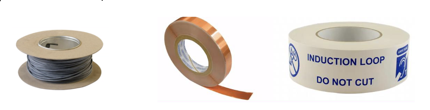
Fig. 1: Cable and flat copper tape for making an induction loop
A special flat copper installation tape (up to 2 cm wide) is used under linoleum, vinyl, laminate or wood flooring or carpet. This needs to be supplemented with warning tape and extruded protective tape according to the nature of the floor on which the material is installed.
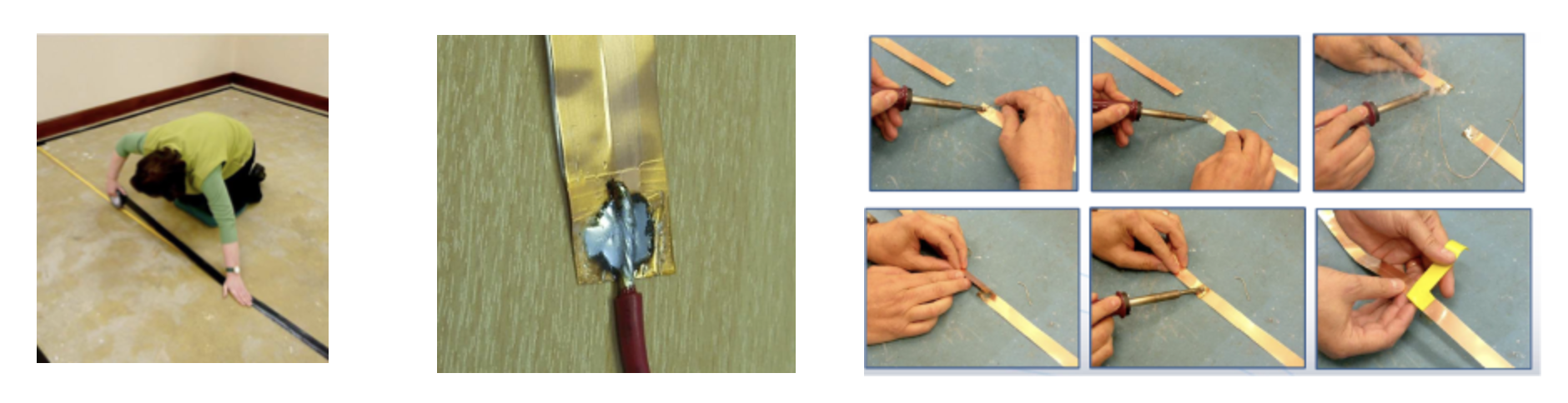
Fig. 2: Examples of laying and connecting copper tape
The amplifier is connected to the induction loop most often by a twisted pair of wires. One wire for the flow of current from the amplifier to the loop, and the other for the return current.
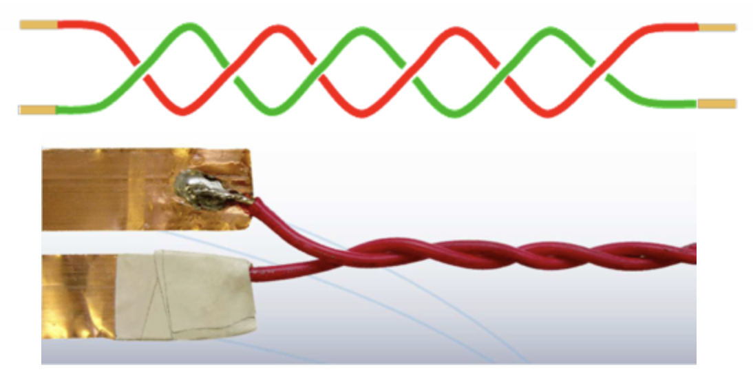
Fig. 3: Connecting the loop amplifier to the induction loop
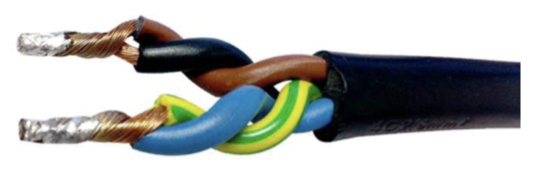
Fig. 4: Connecting the amplifier to the induction loop using a 4-core cable = Starquad system
Used for the phased array field.
The contractor or installation company should ensure the placement of an information sticker with the internationally recognized IL logo showing an ear with the letter „T“ in the lower righthand corner. This provides assurance of a professionally installed induction loop system.
Fig. 5: Internationally recognized logo for the induction listening loop
Induction loop amplifiers are usually installed in a server room [1] with audio equipment. The equipment of the broadcasting amplifier should also include mounts for placing the amplifiers in a 19” (inch) rack, i.e., compatible with the installed technology.
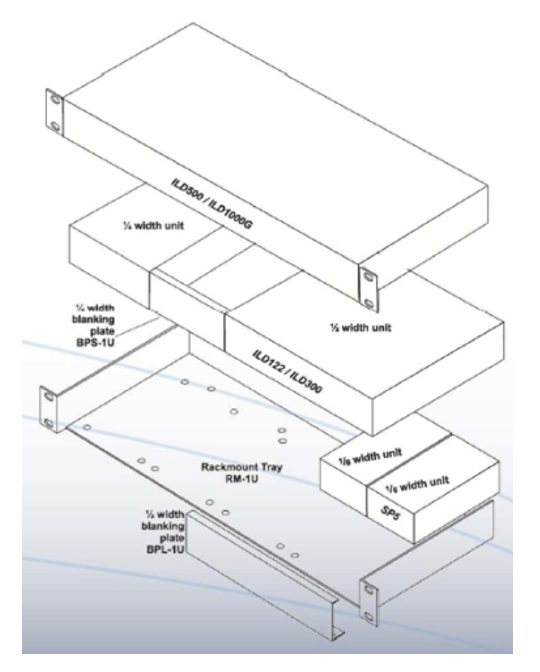
Fig. 6: Example of assembly of individual IL components in a 19’’ rack
[1] A server room refers to specialized air-conditioned spaces where computer servers and other important technological equipment are safely located.
3. Recommendations that must be respected during the design, installation and normal operation of induction listening loops
CORRECT PROCEDURE:
- With a suitable measuring device (see page 9) perform an assessment at the IL installation site of the background electromagnetic noise level and the signal loss in the metal structure of the building.
Test audio files are here:

- Check whether there are steel floor tiles or grids or aluminum suspended ceiling frames at the IL installation site, or whether their use is proposed in the project documentation of the building.
- Check that there is no stage or area where electrical musical instruments are to be used in or near the proposed loop area. If so, the installation of the IL must be adapted to this circumstance.
- Check what the proposed loop area will be used for (seated listening, standing listening, free-moving user, etc.).
- Work with your chosen manufacturer or specialist contractor to calculate the power requirement of the loop system based on the volume of space to be covered and the length and type of loop/power cable.
- Based on the established circumstances, ask the manufacturer or specialist contractor and installation company for the design of individual IL components and the method of making your own induction loop.
- If you are working with a professional contractor and installation company, check directly with the manufacturer, if possible, that the proposed components of your listening induction loop are suitable for the installation and are compatible with each other.
- Carefully choose a suitable microphone for your application. Remember that you are trying to capture only the sounds you want in order to increase the signal-to-noise ratio. Therefore, if possible, choose a directional microphone and make sure it is placed as close as possible to the operator’s mouth. If the microphone is too far from the desired sound source, the unit will not provide any additional benefit over the hearing aid or cochlear implant alone.
- Use the possibility of connecting an external microphone (if the device allows it) and place it as close as possible to the mouth of the person whose voice needs to be captured, e.g., a lapel microphone. CAREFUL!!! If you use a wireless external microphone, the so-called microport, mutual interference between this microphone and the IL may occur. The situation can be solved by having the IL and microport use different channels.
- If you are installing a fixed counter IL, make sure that the pre-shaped loop contained in the counter is attached in a suitable place on the front part of the counter to ensure good listening at the ear level of the intended user (both standing and seated, e.g., for users in a wheelchair).
- Remember that the magnetic field generated by a vertical induction loop can create so-called „dead spots“. Therefore, always check the signal in the entire sound area using a suitable measuring device or an IL receiver and, if necessary, adjust the connection.
- Make sure that the system is wired so that it activates every time the cash register, computer terminal or other device to which it is functionally connected is turned on. The system is inaudible, so it is very easy to forget to turn it on.
- Ensure that appropriate signage is placed at the counter and that it remains visible even though people are standing in line at it.
- When installing an induction loop in the form of a flat copper tape glued to the floor, ensure that the floor is clean, dust-free, dry and free of sharp fragments that could pierce the protective adhesive film and cause the loop to ground.
- When using flat copper tape on a metal floor, use a layer of insulating (non-conductive) tape under the copper tape.
- Use printed warning tape to tape the copper tape to the floor to prevent possible damage when laying carpets or when cleaning or making any adjustments on the floor.
- For the same reason, install a copper tape loop cable several centimeters away from the wall to avoid damage to it during painting, wallpapering, cutting carpets or linoleum, etc.
- Use the controls on the device to optimize the signal and put it into operation according to the requirements of IEC 60118-4.
- Listen to the sound quality of the IL system using a suitable IL receiver and make a note of your subjective evaluation.
- At the entrance to a room with installed IL, ensure the appropriate marking (internationally recognized IL logo). Inside as well.
- If you are a company officially engaged in the design, supply, installation and adjustment of IL systems, put the IL system into operation after installation in accordance with the IEC 60118-4 standard and provide the site manager with a certificate of conformity (see page 10).
If you are not able to correctly evaluate the above findings or adapt the project to them, ask for help with the design from experts who will be able, if necessary, to use comprehensive multi-loop phase systems to perform quality work.
The same applies to the requirement that the system be installed and commissioned in accordance with IEC 60118-4.
In this matter too, it is advisable to turn to experts.
![]()
4. Situations in which mistakes are often made and suggestions on how to avoid them
Unfortunately, even professional supply and assembly companies sometimes make mistakes in this field. Therefore, it is advisable for the IL investor to at least be informed about the issue.
So, if possible, avoid the following incorrect practices:
- Do not select an IL amplifier based solely on the data on the expected coverage of the premises given in the technical specification of the manufacturer. The manufacturer’s data is indicative only. Always perform an appropriate calculation of the required strength of the output power of the amplifier to match the measured values.
- Never ignore the effects of signal loss in a metal structure. Always carry out a careful inspection and measurement of the premises where the IL is to be installed. The result of this measurement can also be the conclusion that the induction loop is not the right solution in the specific case. This danger awaits designers for every building with a modern reinforced concrete structure! At the same time, many underestimate it.
- Do not install the loop around the perimeter of the wall at ear height – never!!! If you do not observe this recommendation, there is a risk of overloading the hearing aid when the IL user is standing close to the wall. This will create an uneven field strength throughout the room, which will worsen the listening conditions for all IL users.
- Do not use omnidirectional ceiling or wall microphones at the input of the IL system (see the previous chapter).
- When putting the IL into operation, do not settle for the loop “sort of working”. As mentioned above, the functioning of the IL system must be checked by listening. Without listening using a suitable receiver and making a subjective assessment, the IL cannot be said to be in working order. Always compare the result with the requirements of the IEC 60118-4 standard and write the result of the subjective assessment in the final measurement protocol (see page 10).
5. Practical recommendations for selecting and setting up portable induction loops
- As with stationary ILs, the correct choice and placement of the microphone is important for portable equipment. If the equipment allows it, use the possibility of connecting an external microphone, which should be placed as close as possible to the mouth of the person whose voice needs to be captured. If an external microphone is not available, then speakers should adjust their position to be as close to the microphone as possible.
- Make sure that the flat side of the portable IL system is facing the person with hearing loss who is using the system and that the equipment has been set at an appropriate distance to ensure comfortable listening.
- Before using it, make sure the equipment is sufficiently charged if there is no power outlet available.
- Make sure that none of the automatic battery shutdown options will shut down the system during operation.
- Perform regular maintenance on the system and batteries and perform regular operational checks using a meter.
- Do not use IL portable partition systems in places where operators are not trained.
- Do not use the listening IL loop label to advertise the system as available in locations where the system is not permanently located (i.e., where only portable equipment is used).
6. Procedures for evaluating and testing the site where IL is installed or where it should be installed
a) Key questions:
- What is the name of the specific place and room?
- What type of system is required?
- Are there drawings of the sound space available at the required scale?
- Is signal overlap a problem for surrounding systems in terms of mutual interference or confidentiality?
- Is there a metal structure in the building or sound area?
- Where specifically can or should the loop(s) be installed?
(i.e., floor, ceiling, interior or exterior room walls, other options…).
b) What to measure and how:
- For installed ILs, measure the compliance of the function of the induction loop system with the requirements of the international standard IEC60118-4. Measure with a test loop and measuring device for measuring the electromagnetic field. There are many manufacturers and suppliers of such devices. E.g., Audioropa, Ampetronic, Connevans, Opus, Contact. (See page 9, point e) of this chapter).
- The device measures the performance of the installed induction loop system. Three calibrated operating modes are measured: Noise, Field Strength and Frequency Response.
- The measuring device generally also works as an induction loop receiver via headphones. Thanks to this, the person performing the measurement can easily check the quality of the final listening of the signal transmitted by the loop.
- The device should be part of the equipment of every technician or institution providing services for optimizing the use of IL.
- The following are also measured: background noise (minimum – 22 dB) and losses in metal structures.
c) Testing procedure:
- Use calibrated measuring equipment (e.g., FSM, CMR3, sound analyzer and others, see page 9 – point e).
- Find the farthest point on the perimeter to be tested.
- In the input socket of the tester, connect the test leads to the “Line, Neutral and Earth”
terminals. - Measure and record the results.
- Compare the measured results with the IEC60118-4 standard.
- If there is a mismatch, adjust the power of the loop transmitter or adjust the shape and location of the loop, or both.
Practical notes and recommendations:
- When in doubt, test the induction loop around the perimeter first. However, if the measured IL is required to extend the signal outside the sound area, the perimeter test is only indicative.
- The test loop should be placed close to the existing induction loop.
- Select the appropriate measurement loop width for testing.
d) What to record?
- The actual dimensions of the loop in the sound space.
- Height/position of the signal measurement (where and at what height is the test loop located).
- Test signal (typically a 1 kHz sine or combination signal).
- Loop current (RMS).
- Measured magnetic field strength.
- Configuration of the test loop (length, width, location – height from the floor or ground, material, etc.).
e) Measuring the performance of the induction loop system – measuring instruments:
Currently, there are a number of measuring devices for performing the objective measurement of IL parameters. Below are some examples:
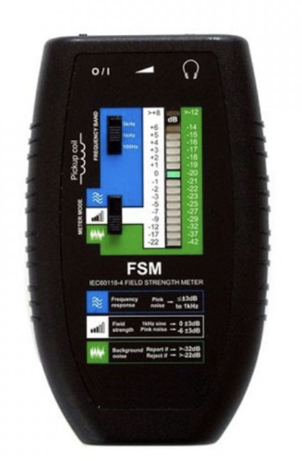
Fig. 7: FSM meter
FSM
A simple device for measuring, setting up and an induction loop system into operation according to the requirements of IEC60118-4. The FSM meter offers three calibrated operating modes to evaluate background noise, field strength, and frequency response. External headphones can be connected to determine the signal level in the loop and subjectively assess the quality of the audio transmission.
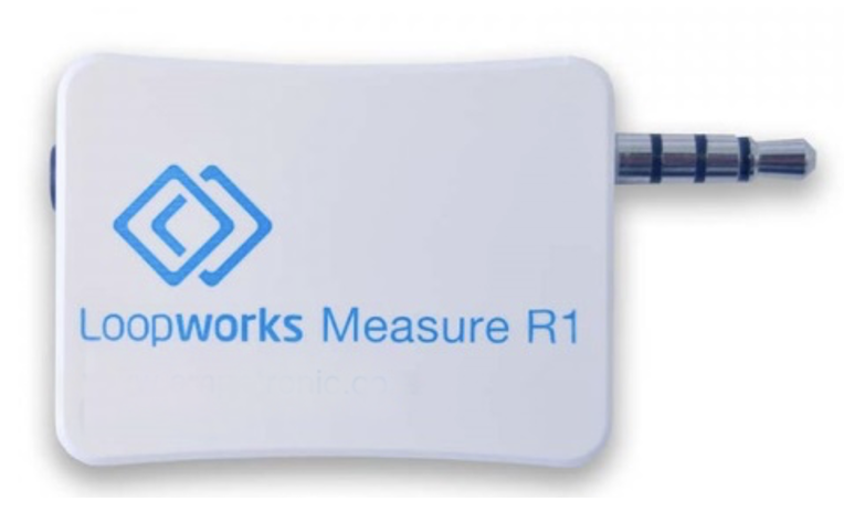
Fig. 8: Loopworks Measure instrument
- Superb, self-calibrating audio induction loop receiver for detecting the induction field of a vertically connected receiving coil. The receiver can be connected to an iPad or iPhone.
- The measurement is in accordance with the IEC 60118-4 standard.
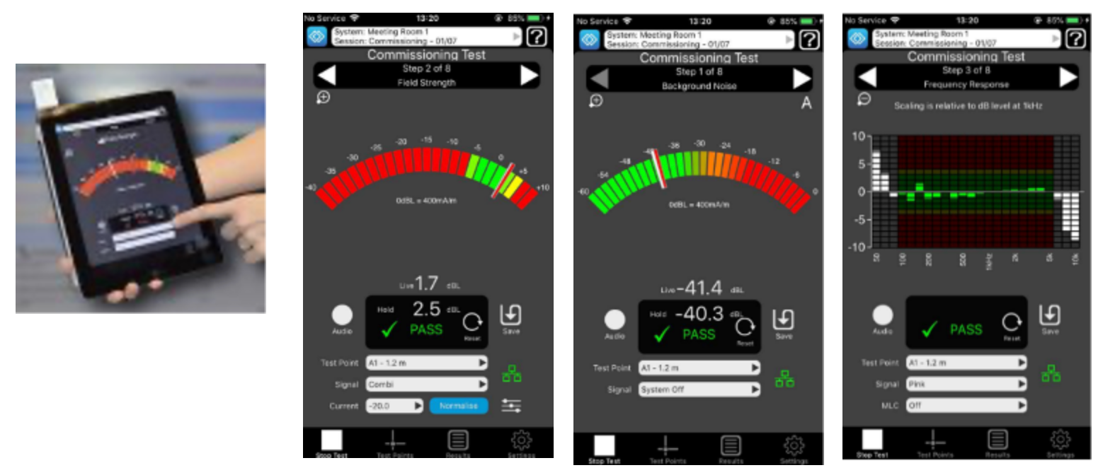
Fig. 9: Connecting Loopworks Measure R1 instrument to an iPad
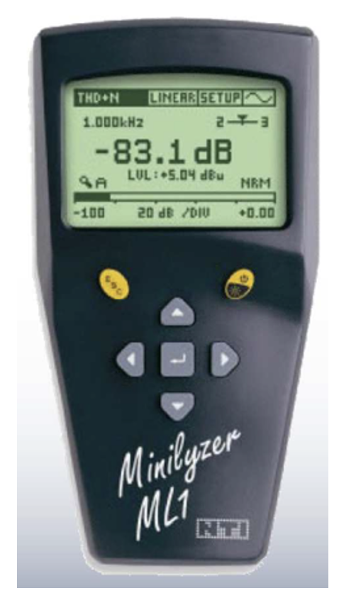
Fig. 10: Minilyzer ML1 NTI – loop receiver + meter for all basic IL parameters
7. Putting the induction loop into operation
As often mentioned in the previous text, it is necessary to ensure that all European and national standards (Czech, Slovak and Slovenian) are fully met during the installation and commissioning of the IL.
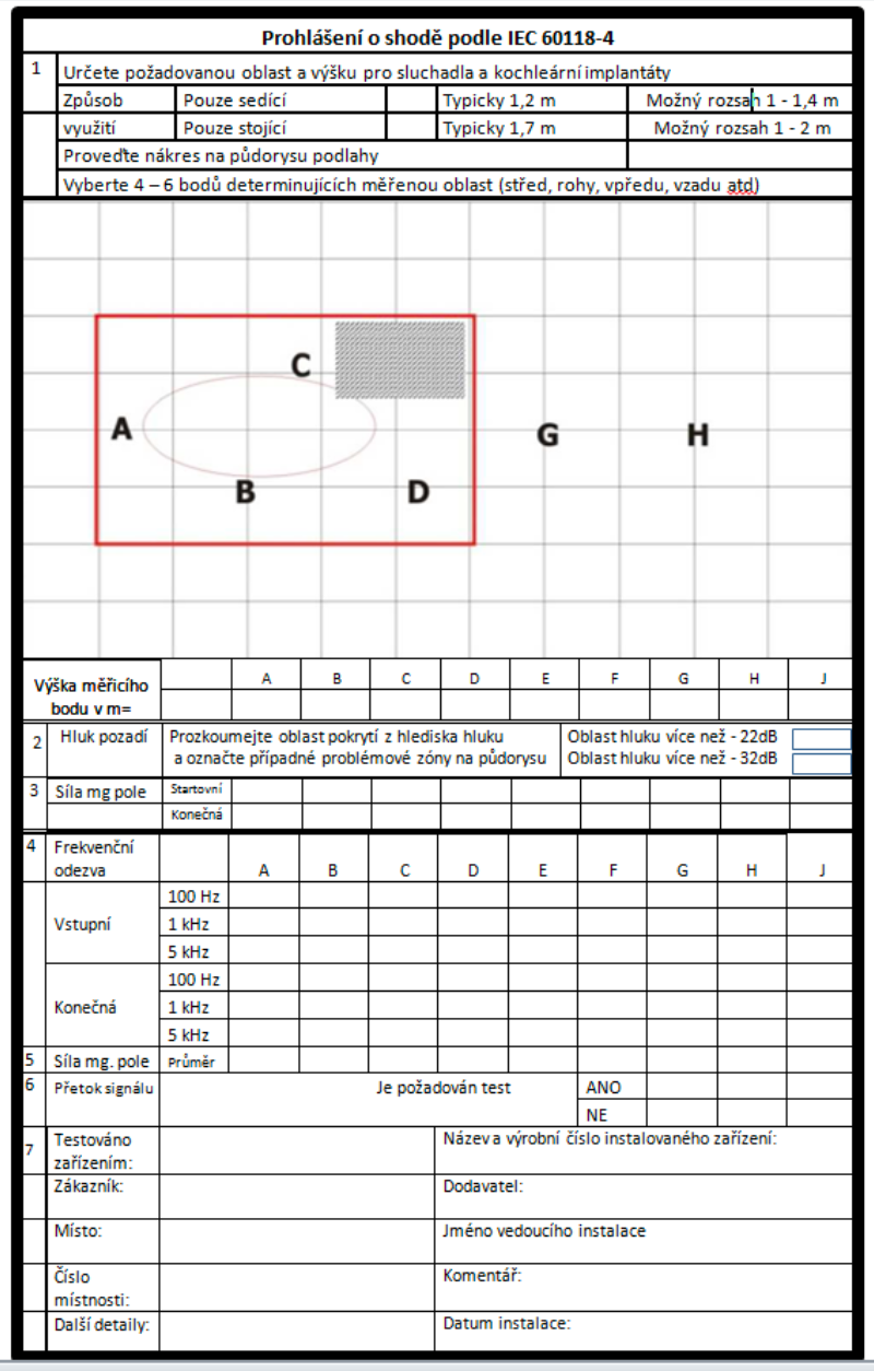
The supplier and assembly company (if they are not the same company) are obliged to confirm to the customer compliance with the standards and possibly other regulations by the Declaration of Conformity.
Table 2: Declaration of Conformity
Annex to Part 2 of the methodology
Induction loops in transport
Transport offers vast possibilities for the use of IL. In the developed countries of Europe and on the North American continent, IL serves people with hearing impairment in many aspects of travel and transport. Typical places where IL can be found are, for example:
Stations and airports:
- ticket counters – whether automatic without an attendant or classic ticket counters with an attendant;
- manned check-in counters;
- automatic terminals for unattended flight check-in;
- information points, automatic without an attendant or with an attendant;
- first aid stations;
- train station or airport announcements – if the announcement is not simultaneously broadcast by an induction loop, it is unintelligible to passengers with hearing impairments even after being amplified by their hearing aids (masking by ambient noise + strong echo)
- elevators in check-in halls, on platforms, at individual “gates”, etc.;
- intercom when entering a parking lot controlled by a barrier or traffic light, enabling communication with the parking attendant if necessary.
Therefore, the chapter dedicated to IL in transport is presented as separate, yet only informative material. All project partners will understandably strive to make the implementation of IL in transport more pronounced in the partner countries and throughout Europe. Project outputs should contribute to it, including this tutorial.
![]()
Sound information in transportation (train, tram, metro…)
This category of IL usage requires technically sophisticated solutions. The problem is the variable conditions under which the IL system has to deal with various disturbances. Losses in the metal constructions of the means of transport, sparking generated by the friction of pantographs against the power wire, disruptive electromagnetic fields generated by thyristors controlling the electric motors of the means of transport, and other time-varying influences inside and outside trams, metros, trolleybuses, etc. Also relevant is the requirement for vehicle operators to ensure that the IL does not interfere with wireless links used for communication between drivers and their control room. It is also necessary to address the situation where, for example, two (or even more) means of transport meet at a station at a minimum distance, and each of them has an IL transmitting different information (e.g., lists of stations that are different for different lines). The flux of the magnetic field from ILs installed in these means of transport must be minimal. These and many other requirements for IL systems in vehicles can only be met with a wealth of experience and theoretical expertise. Only with their use can a special “tailor-made” loop amplifier and complex loop system be designed to solve the above requirements and problems.
![]()
Current status of the use of il in transport in the partner countries of the project
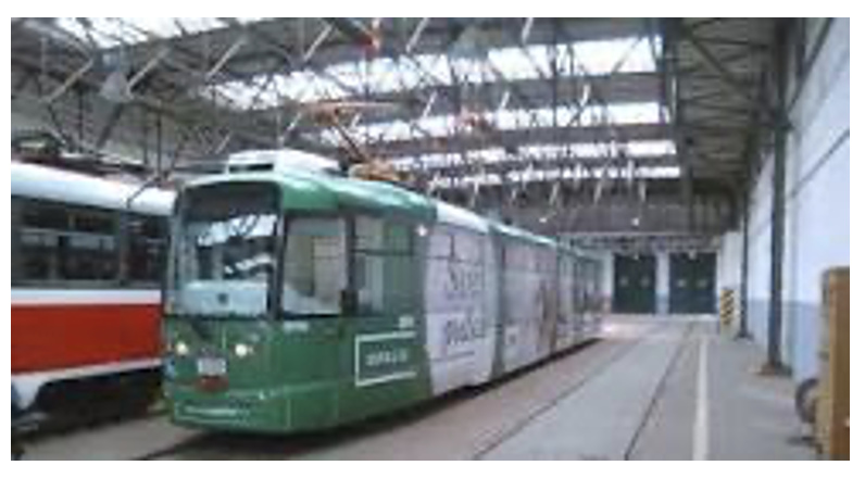
Among the partner countries of the project, Slovakia is currently the furthest along in this area. In the city of Košice, there are 46 Vario LF2 trams equipped with an induction loop for the hearing impaired.
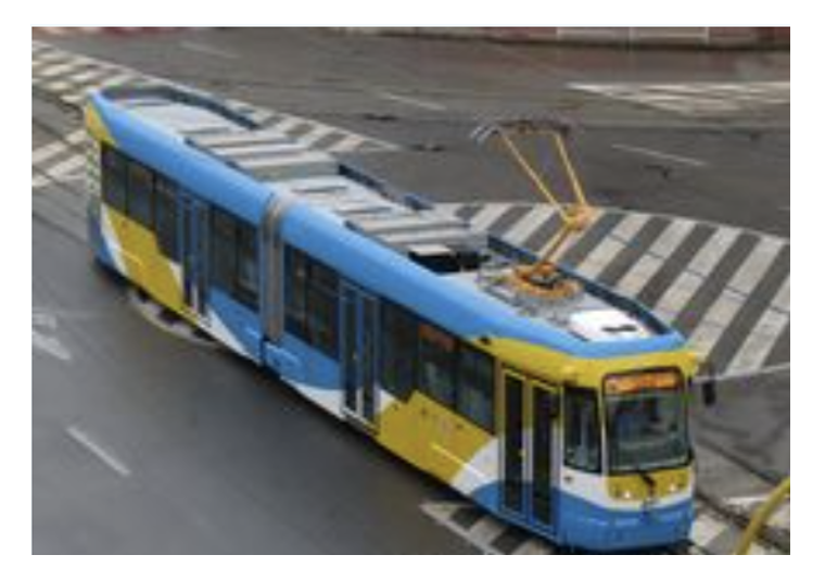
In the Czech Republic, the “first swallow” tram is equipped with IL and runs regularly in Brno thanks to the cooperation of the project coordinator (Union of the Deaf in Brno) and the Transport Company of the City of Brno.
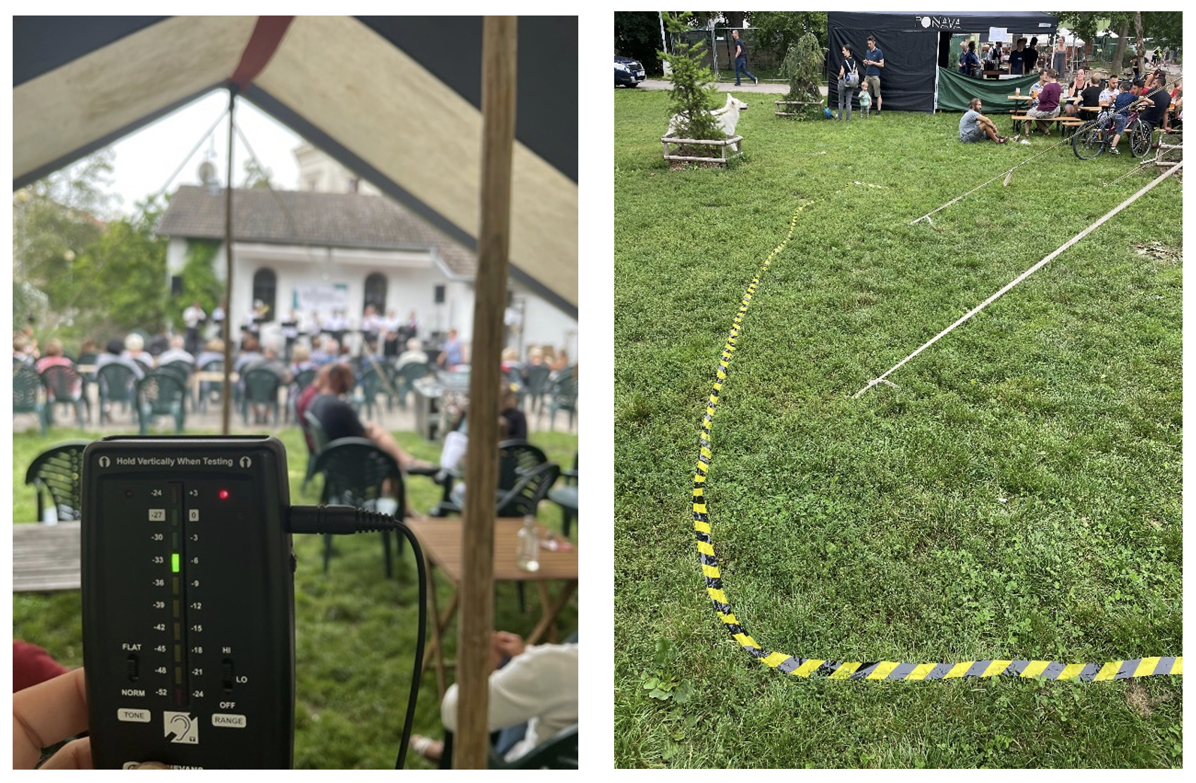
Other examples of using induction loops outside the area of transport
Measuring the IS signal at the Babské leto event in 2021 in Lužánky, Brno
Demonstration of IL preparation and involvement in the Auditorium in Prague
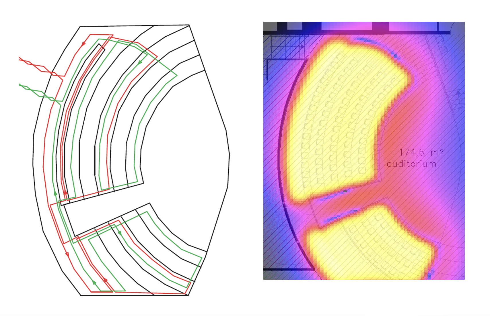
Proposed connection and IL signal visualization
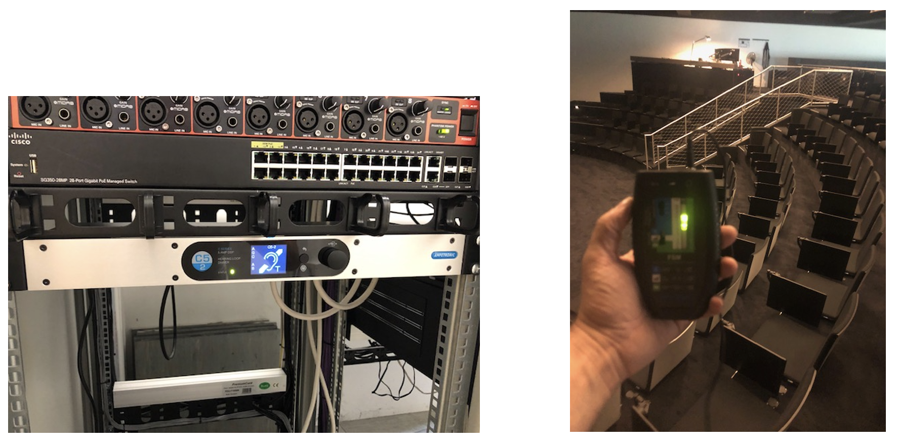
IL amplifier and Signal measurement
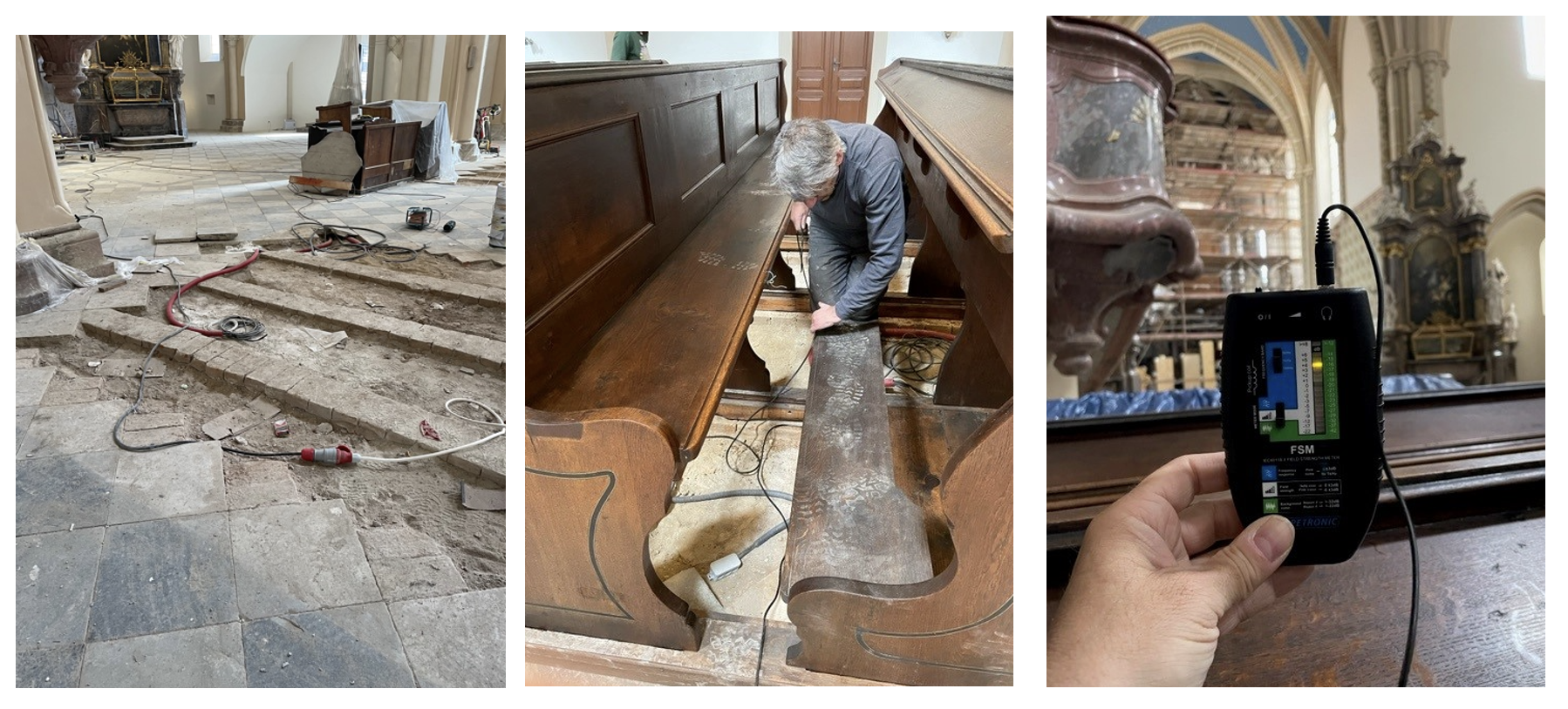
IL installation in the church of Porta Coeli u Tišnova
![]()